

Seven types of noise inside the pressure sensor circuit - Kiel Planck
  • Home
        • New Product

          Seven types of noise inside the pressure sensor circuit - Kiel Planck

          There is a solution for every application. Let’s work together to find the right solution for you.

          Your benefits

          We use our experience to move your project forward.

          PHONE: 400-8868-261

          E-mail: info@kielplanckprc.com / kielplanck@outlook.com

  • Application
  • Service
  • Brand
  • Blog
  • Contact Us

Seven types of noise inside the pressure sensor circuit

Seven types of noise inside the pressure sensor circuit

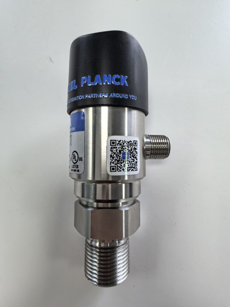
During industrial signal acquisition, pressure sensors generate various inherent noises within their circuitry. These are inherent interferences of the device itself and cannot be completely eliminated, directly affecting measurement accuracy and signal stability.
Seven types of noise inside the pressure sensor circuit - Kiel Planck

Internally, noise in the circuit can be mainly categorized into seven types: thermal noise, shot noise, 1/f flicker noise, burst noise, parasitic resonance noise, leakage current noise, and mutual inductance coupling noise. These are the main internal causes of sensor data drift, fluctuations, and instantaneous jumps.

Thermal noise, also known as Johnson noise, is generated by the random thermal motion of electrons within the device. It increases with temperature and is a type of white noise across the entire frequency range. It causes signal baseline fluctuations and affects static measurement accuracy. Shot noise originates in the semiconductor PN junction. The discrete migration of charge carriers causes current fluctuations. The higher the operating current, the more significant the noise. After amplification by the amplifier circuit, it reduces the detection resolution of weak pressure signals.

1/f flicker noise is low-frequency noise. Its power increases as the frequency decreases. It is mostly caused by chip surface defects, material inhomogeneity, and poor contact. It is the main reason for zero-point drift and slow fluctuations in steady-state data during long-term sensor operation.

Popping noise, commonly known as popcorn noise, is caused by semiconductor lattice defects and impurity inhomogeneity. It manifests as irregular, sudden current pulses, causing instantaneous data jumps and easily leading to misjudgments in control systems.

Parasitic resonance noise originates from the parasitic inductance and capacitance of PCB circuits and components. During high-frequency operation, it forms a resonant circuit, causing waveform distortion and dynamic response inaccuracy, severely affecting detection accuracy under conditions of rapid pressure fluctuations. Leakage current noise is caused by unstable leakage current resulting from insulation aging and moisture accumulation. This leakage current is superimposed on the effective signal, increasing measurement errors, and is particularly prominent in harsh industrial environments.

Mutual inductance coupling noise is crosstalk generated by the mutual inductance coupling of magnetic fields between adjacent circuits and components within the circuit. It is significant in high-density PCB circuits, causing output signal fluctuations and decreased stability. These seven noise sources cover all interference sources under various operating conditions. In practical applications, noise can be suppressed by optimizing wiring, selecting low-noise components, strengthening insulation, and using temperature control for noise reduction, effectively improving the detection stability and accuracy of pressure sensors.

Scan the QR code to receive more detailed information.

Seven types of noise inside the pressure sensor circuit - Kiel Planck

Share:

More Posts

How to Measure Inlet Gas Flow of Water Electrolysis Hydrogen Production Units? - Kiel Planck

How to Measure Inlet Gas Flow of Water Electrolysis Hydrogen Production Units?

Stable and accurate inlet gas flow monitoring is the core prerequisite for efficient and safe operation of water electrolysis hydrogen production equipment. The inlet raw gas of electrolytic hydrogen production features low viscosity, high cleanliness and mild operating pressure, putting forward specific requirements for flow measurement instruments. As a high-precision, fast-response speed-type measuring device, gas turbine flow meters are gradually applied in hydrogen production inlet pipeline monitoring.

Do Not Use Turbine Flow Meters for These Media: List of Six Unfavorable Working Conditions - Kiel Planck

Do Not Use Turbine Flow Meters for These Media: List of Six Unfavorable Working Conditions

Turbine flow meters are widely recognized for their high accuracy, excellent repeatability and fast dynamic response, making them mainstream equipment for industrial fluid custody transfer and precise process metering. However, their core rotating impeller and precision bearing structure determines strict limitations in medium adaptability. Blind application in inappropriate working conditions easily causes bearing abrasion, impeller deformation, signal failure and rapid performance attenuation

How to Solve Vortex Flow Meter Probe Fouling and Corrosion - Kiel Planck

How to Solve Vortex Flow Meter Probe Fouling and Corrosion

Vortex flow meters rely on bluff body probes to generate regular Karman vortex streets, making probe surface condition the key to stable and accurate flow measurement. In industrial scenarios such as chemical production, sewage treatment, steam pipelines and brine transportation, probes are prone to scaling, adhesive fouling and electrochemical corrosion after long-term operation. Damaged probe surfaces disrupt vortex generation, cause signal jitter, measurement deviation and even meter failure.

Vortex Flow Meters Need No Temperature and Pressure Compensation” - Kiel Planck

Vortex Flow Meters Need No Temperature and Pressure Compensation”

A widespread misconception in the industrial instrumentation industry claims that vortex flow meters operate accurately without temperature and pressure compensation. This simplified but misleading statement has misled numerous purchasers and engineering teams into improper configuration, resulting in severe measurement deviations, inaccurate energy statistics and unqualified custody transfer data.

Send Us A Message

captcha
Reload

Bitte geben Sie die im CAPTCHA angezeigten Zeichen ein, um sicherzustellen, dass Sie ein Mensch sind.

Email
Email: info@kielplanckprc.com
WhatsApp
WhatsApp Me




