

Pressure switches serve as core protective components within industrial pressure control systems; the precision of their actuation and reset pressures directly impacts equipment operational safety and process stability.
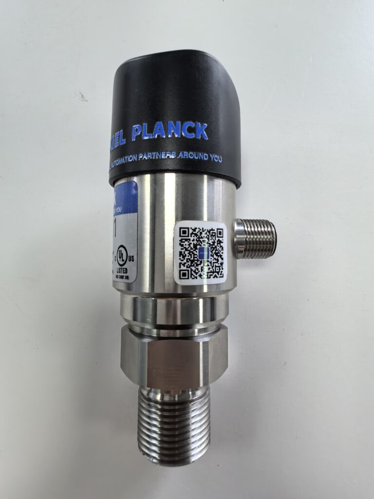
To eliminate errors caused by zero-point drift, mechanical wear, and elastic fatigue resulting from long-term operation, periodic calibration using a pressure calibration pump and precision pressure gauge is necessary to ensure that the pressure switch’s start-stop parameters meet equipment technical standards. The entire calibration process is standardized and its accuracy is controllable, making it the most common method for pressure switch verification in industrial settings.
Before calibration, thorough equipment preparation and safety checks are essential. The core calibration equipment consists of a manual pressure calibration pump and a high-precision standard pressure gauge. The precision pressure gauge must have an accuracy class of at least 0.4 and be within its calibration validity period to ensure accurate and reliable measurement data. Simultaneously, prepare auxiliary tools such as a multimeter, terminal blocks, and wrenches. Clean oil and impurities from the pressure switch’s pressure tapping interface and check the pipeline’s sealing to prevent air or oil leaks from affecting calibration accuracy. Before operation, disconnect the power supply and media pipelines connected to the pressure switch, release any residual pressure in the equipment, and implement safety precautions to eliminate the risks of working under pressure or electricity.
Formal calibration begins with equipment connection and zero-point verification. The pressure calibration pump, precision pressure gauge, and pressure switch are connected in series via dedicated piping, ensuring a tight, leak-free connection. Simultaneously, a multimeter is set to the continuity setting and connected in parallel to the pressure switch signal contact to monitor its operation. After connection, the equipment is left to stand for a moment, and the precision pressure gauge pointer is observed to return to zero. If a zero-point deviation exists, the zeroing knob on the pressure gauge is fine-tuned to complete the initial zero-point calibration, ensuring error-free basic measurements.
Subsequently, pressure calibration for the pressure increase operation is performed. The pressure calibration pump is operated slowly and uniformly to increase pressure, controlling the rate of increase to avoid sudden pressure spikes that could distort the calibration data. The readings on the precision pressure gauge and the continuity status of the multimeter are observed in real time. When the pressure switch contacts switch on and off, pressurization is immediately stopped, and the reading on the precision pressure gauge is recorded. This value is the actual operating pressure of the pressure switch. The measured value is compared with the equipment’s rated operating pressure. If a deviation exists, the internal adjusting screw of the pressure switch is adjusted, and the pressure increase test is repeated until the measured value matches the standard value.
After the actuation pressure calibration is completed, the pressure reduction and reset pressure verification is performed. Slowly loosen the pressure relief valve of the calibration pump to uniformly reduce the system pressure, closely observing the pressure gauge readings and multimeter status. When the pressure switch contacts reset and switch on/off states, record the current pressure value; this is the reset pressure. Similarly, fine-tune the switch parameters according to the technical standards, repeating the test 2 to 3 times to ensure that the actuation pressure and reset pressure values are stable and the error is within the allowable range.
In the final calibration stage, close the pressure relief valve of the calibration pump, slowly release all pressure in the pipeline, disconnect the connecting pipelines and testing lines, tidy up tools and equipment, record the calibration data, and label the calibration date and verification results. Throughout the entire calibration operation, the pressure rise and fall must be kept stable, preventing sudden pressure changes, and ensuring good pipeline sealing. By verifying the coordination between a precision pressure gauge and the pressure calibration pump, pressure switch deviations can be effectively corrected, ensuring accurate triggering of protective actions in the industrial control system and avoiding the risk of overpressure operation.
Scan the QR code to receive more detailed information.





