

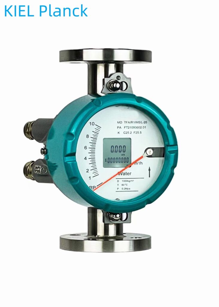
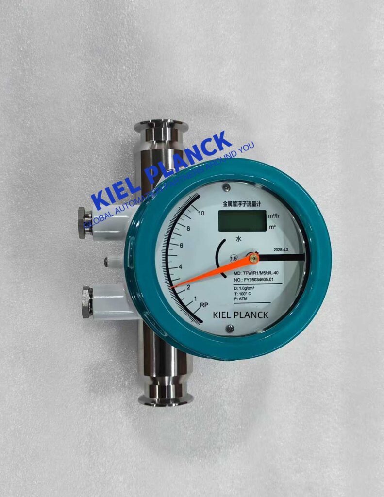
Metal float flowmeters measure flow rate by changing the position of the float in a tapered tube. The core principle is variable area flow measurement, which utilizes the pressure difference generated by the fluid passing through the annular gap between the float and the tapered tube and the balance of the float’s weight to convert the flow rate into a linear relationship with the float’s height.
I. Basic Working Principle
Core Measurement Mechanism
When the fluid being measured flows upward through the vertical conical measuring tube, the float moves upward due to the thrust of the fluid.
When the float rises to a certain position in the conical tube, the thrust of the fluid on the float and the weight of the float reach equilibrium, at which point the float stabilizes at that position.
The float height has a linear relationship with the flow rate; the flow rate can be determined by measuring the float’s position.
Force Balance Process
The float is subjected to three forces: fluid thrust (upward), float weight (downward), and fluid buoyancy (upward). (Above)
When the fluid flow rate increases, the thrust increases, the float rises, the annular area increases, the flow velocity decreases, and the thrust decreases.
When the thrust and gravity are balanced, the float stabilizes at a certain height, which is proportional to the flow rate.
II. Correspondence between Float Position and Flow Rate
Variable Area Mechanism
The higher the float is in the conical tube, the larger the annular flow area between the float and the conical tube.
The annular area is linearly proportional to the float’s rising height, meaning that a certain float height represents a specific flow rate value.
The basic equation for volumetric flow rate Q is:
Q = α·√(2gH)
Where α is the flow coefficient, g is the gravitational acceleration, and H is the float height.
Measurement Accuracy Guarantee
The float is typically made of high-density materials (such as stainless steel and copper alloy) to ensure measurement stability.
The inner wall of the tapered tube is precision-machined to ensure a linear relationship between the float position and flow rate.
Accuracy can reach ±1.0%, and special models can reach ±0.5%, meeting the high-precision measurement needs of industry.
III. Signal Conversion and Output System
Magnetic Coupling Transmission Principle
A high-performance permanent magnet is embedded inside the float to form a stable magnetic field.
An external magnetic sensor is installed, and the change in float position is converted into an electrical signal through magnetic coupling.
Non-contact transmission avoids the risk of fluid leakage and enables remote transmission.
Signal Processing and Output
Local Indication Type: The flow rate value is directly displayed on the dial by a pointer driven by magnetic coupling.
Intelligent Remote Transmission Type: The magnetic sensor converts the change in magnetic field into an electrical signal. After A/D conversion and microprocessor processing:
Outputs a 4-20mA standard current signal
Displays instantaneous flow rate and cumulative flow rate
Supports HART communication protocol for parameter setting
IV. Flowmeter Structure
Core Measuring Components
Conical Measuring Tube: A metal tube that gradually widens from bottom to top, usually made of stainless steel.
Float: A rotor that can move up and down along the axis of the conical tube; various shapes are available (spherical, cylindrical, dumbbell-shaped, etc.).
Guiding System: Ensures the float moves vertically, reducing measurement errors.
Signal Processing Components
Indicator: Includes a mechanical pointer or LCD display.
Converter: Converts the float displacement signal into a standard electrical signal.
Magnetic Coupling System: Composed of the float’s built-in magnet and an external magnetic sensor.
V. Installation and Usage Guidelines
Correct Installation Method
Must be installed vertically, with an inclination angle not exceeding 2°, ensuring fluid flow from bottom to top.
A straight pipe section of at least 5 times the pipe diameter is required at the inlet, and a straight pipe section of 250mm is required at the outlet.
If the medium contains ferromagnetic substances, a magnetic filter should be installed to prevent the float from jamming.
Flow Measurement Range
The range ratio is typically 10:1, with special models reaching 20:1 or 50:1.
Can measure flow rates from small to large, suitable for liquids, gases, and steam.
Suitable for harsh environments such as high temperature, high pressure, and strong corrosion.
VI. Advantages in Practical Applications
Multi-Media Adaptability
Measuring liquids, gases, and steam; suitable for corrosive, high-viscosity, or particulate media.
Cone and float materials are available in stainless steel, Hastelloy, titanium alloy, etc., to meet the needs of different media.
High Reliability
Simple and robust structure; no easily damaged electronic components directly involved in measurement.
Low maintenance; service life of over 10 years.
Low requirements for straight pipe sections; flexible installation; adaptable to various pipeline layouts.
The metal float flow meter achieves high-precision and high-reliability measurement of industrial fluid flow by converting flow rate into float height through a direct measurement method, combined with magnetic coupling signal transmission technology. Its simple structure and strong adaptability make it the premier flow measurement instrument for industries such as chemical, petroleum, pharmaceutical, food, and water treatment, especially suitable for flow measurement scenarios of small-diameter and low-velocity media.
Scan the QR code to receive more detailed information.





