

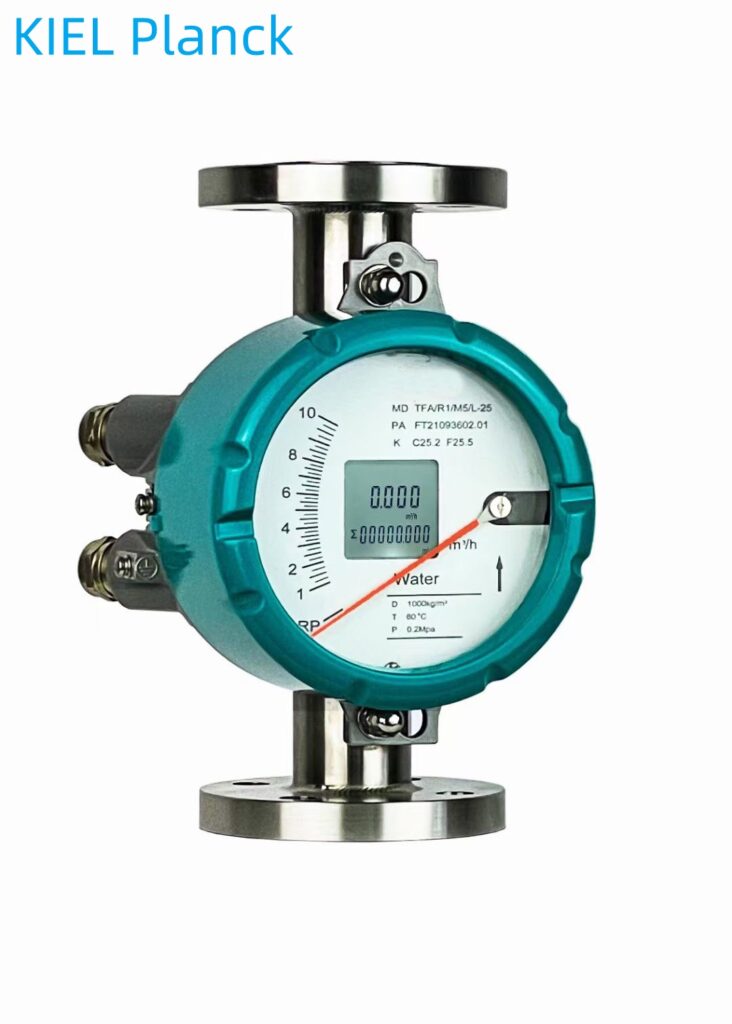
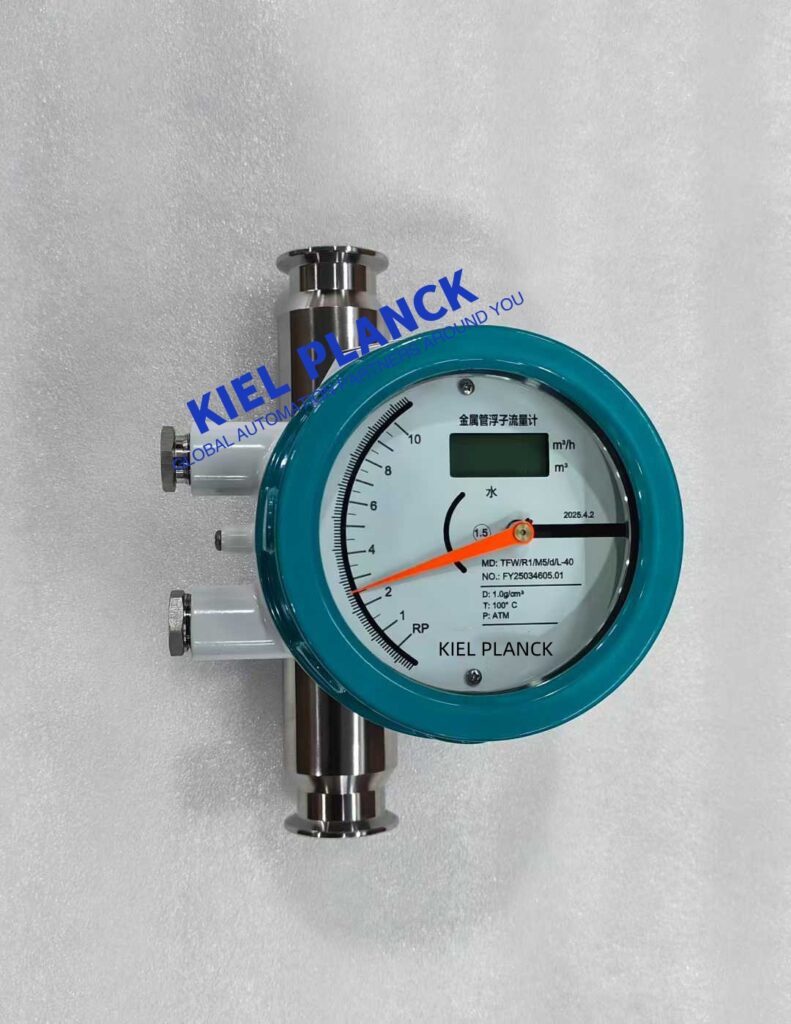
The main reasons for inaccurate measurements by metal tube rotor flowmeters can be summarized into five categories: improper selection, improper installation, changes in media characteristics, equipment failure, and environmental interference. Among these, improper installation and changes in media characteristics are the most common reasons, accounting for more than 70% of actual failures.
I. Measurement Errors Due to Improper Selection
1. Inappropriate Diameter Selection
* **Oversized Selection:** When process conditions change, leading to a decrease in actual flow rate, an oversized selection in the original design effectively raises the lower limit of measurable flow, resulting in unreliable indication at low flow rates.
* **Undersized Selection:** Flow rates exceeding the instrument’s range cause the float to become stuck at the top, preventing accurate flow measurement. Prolonged operation beyond the range accelerates equipment wear.
2. Inappropriate Material Matching
* **Corrosive Media:** Failure to select appropriate materials based on the corrosiveness of the medium. For example, failing to use Hastelloy or titanium when measuring concentrated sulfuric acid leads to rapid corrosion of the float or conical tube, causing geometric changes and measurement errors.
* **High-Temperature Media:** Failure to select high-temperature resistant materials results in PTFE lining decomposition or thermal expansion of metal components, affecting float stability.
3. Failure to Consider Media Characteristics
* **High-Viscosity Media:** Failure to select a dedicated flow meter with optimized float shape and material leads to significant impacts of viscosity changes on float movement resistance.
Containing solid particles: The lack of a filter or the use of a hard alloy float causes particulate matter to accumulate on the upstream side of the vortex generator, altering the flow coefficient.
II. Measurement problems caused by improper installation
1. Verticality not meeting requirements
Inclined installation: Metal tube rotor flowmeters must be installed vertically, with an inclination not exceeding 2°. Otherwise, the float will be compressed by lateral forces, unable to move freely up and down, causing meter jamming and measurement errors.
1. Horizontal Installation: Conventional metal tube rotor flowmeters are strictly prohibited from horizontal installation. Only specially designed horizontally installed flowmeters can be used in horizontal pipelines.
2. Insufficient Straight Pipe Section
Inlet Straight Pipe Section Too Short: The flowmeter inlet should have a straight pipe section at least 5 times the pipe diameter. Insufficient straight pipe section will lead to unstable fluid flow and affect measurement accuracy.
Outlet Straight Pipe Section Insufficient: The outlet should have a 250mm straight pipe section; otherwise, it will affect the fluid flow state and cause fluctuations in the measured value.
3. Improper Installation Location
Proximity to Disturbance Sources: Installation locations too close to valve diameter changes, pump outlets, or process pipeline bends will cause significant fluid disturbance and affect measurement stability.
Failure to Consider Fluid Flow Direction: Fluid must pass through the flowmeter from bottom to top. Incorrect flow direction will cause the float to malfunction.
III. Measurement Errors Caused by Changes in Medium Characteristics
1. Impact of Density Changes
Liquid Media: Since the instrument is converted based on the density provided by the user before calibration, significant changes in medium density will cause large measurement errors.
1. **Gas Media:** Gas density is significantly affected by temperature and pressure. Without temperature and pressure compensation, measurement values will be severely distorted.
2. **Temperature Changes:**
Geometric Dimension Changes: Temperature changes cause variations in the width of the vortex generator and the inner diameter of the pipe, affecting the flow coefficient. The K-coefficient needs correction.
3. **High/Low Temperature Media:** Using a jacketed flow meter can lead to excessively high or low temperatures, causing crystallization and affecting float movement.
4. **Medium State Changes:**
**Air Bubbles or Impurities:** Air bubbles in liquids or droplets in gases alter the medium density, affecting measurement accuracy.
**Pulsating Flow:** Pulsating flow causes continuous changes in the force on the float, resulting in pointer jitter or numerical fluctuations.
5. **Equipment Failures and Insufficient Maintenance:**
1. **Float Jamming:**
**Impurity Accumulation:** Rust, particulate matter, and viscous dirt in the medium adhere to the gap between the float and the conical tube, blocking the flow channel.
**Fourth:** Guide mechanism wear: Wear and deformation of the guide mechanism causes the float’s trajectory to deviate, resulting in rubbing and jamming against the pipe wall or guide components.
Stop deformation: Opening the valve too quickly causes the float to impact the stop rapidly, deforming the stop and jamming the float.
2. Indicating system malfunction
Pointer jitter: Slight jitter can be addressed by increasing damping; severe jitter may be due to medium fluctuations or incorrect installation.
No display or abnormal signal: Poor power contact, loose wiring, or damaged internal circuitry can prevent normal display or signal transmission.
Magnetic coupling failure: Magnet deterioration or excessive gap in the magnetic coupling system can lead to unstable signal transmission.
3. Lack of periodic calibration
Long-term lack of calibration: This can cause scale misalignment and decreased accuracy of the transmitter module, affecting measurement accuracy.
Parameter not updated: Failure to recalibrate the instrument according to actual medium parameters can result in a flow coefficient that does not match the actual value.
V. Environmental interference
1. Vibration effects
Pipeline vibration: Vibration is transmitted to the instrument, causing the float and display components to resonate, resulting in fluctuations in measured values.
Lack of vibration damping: In conditions of strong vibration, such as at the pump outlet, pipeline support is not added to reduce vibration transmission.
2. Electromagnetic interference
Ferromagnetic materials: The presence of ferromagnetic materials within 100mm of the flowmeter can interfere with the normal operation of the magnetic coupling system.
Electromagnetic interference: The lack of electromagnetic protection measures leads to interference with signal transmission.
3. Inappropriate Temperature Environment
High Temperature Environment: Failure to avoid direct sunlight or environments ≥65℃ can lead to aging of the LCD module or degradation of the lithium battery capacity.
Low Temperature Environment: Lack of insulation measures can cause medium crystallization, affecting measurement.
VI. Solutions and Prevention Recommendations
Accurate Selection: Select the appropriate diameter, material, and model based on medium characteristics, temperature, pressure, and other parameters; customized design may be necessary.
Standardized Installation: Strictly adhere to the three core principles of “vertical installation, fluid from bottom to top, and straight pipe section compliance” to ensure measurement accuracy.
Regular Maintenance: Clean the float and inside the pipe monthly to prevent deposit accumulation; perform calibration every six months to verify signal output consistency.
Media Handling: Install filters for solid impurities; configure magnetic filters for ferromagnetic substances; use dedicated flow meters for high-viscosity media.
Parameter Correction: For media with significant density variations, the actual density is substituted into the formula to calculate the error correction coefficient, improving measurement accuracy.
Environmental Optimization: Avoid installing the flow meter in direct sunlight, high temperatures, humidity, or corrosive gas environments; install a protective cover if necessary.
The measurement accuracy of metal tube rotor flow meters directly affects the reliability of production process control. Through proper selection, standardized installation, regular maintenance, and parameter correction, measurement inaccuracies can be effectively resolved, ensuring long-term stable operation of the flow meter in complex industrial environments and providing accurate and reliable flow data support for the production process.
Scan the QR code to receive more detailed information.





