

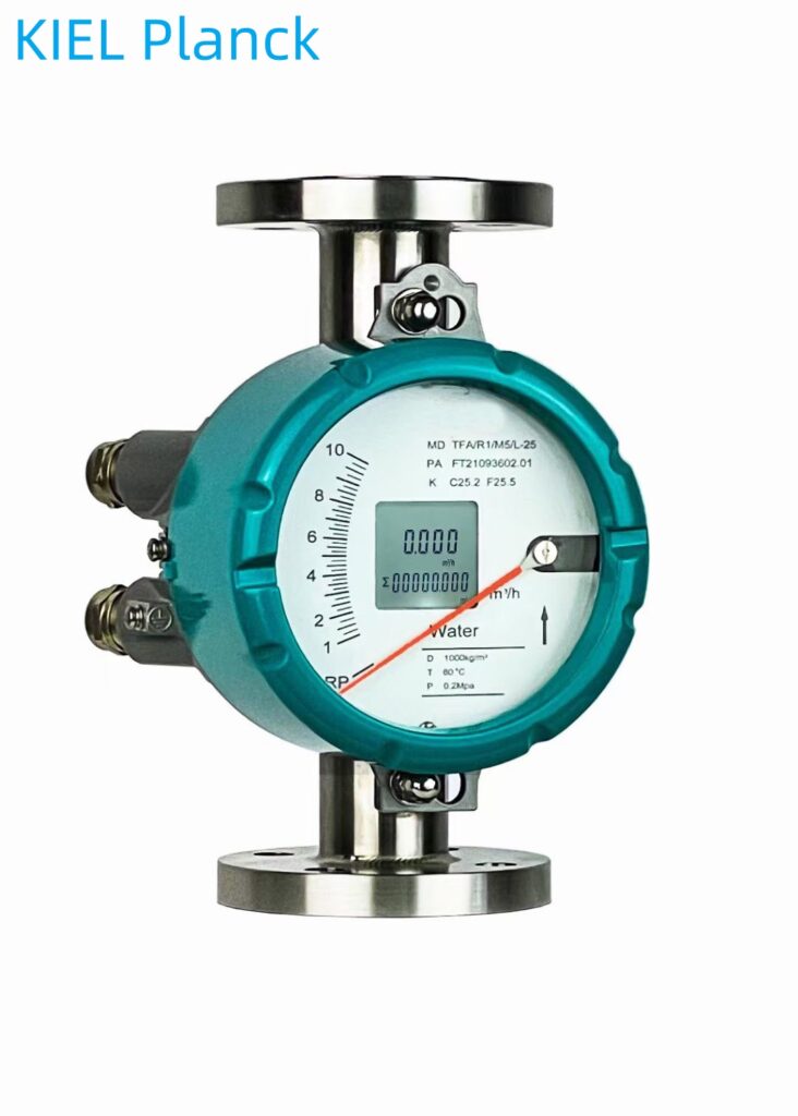
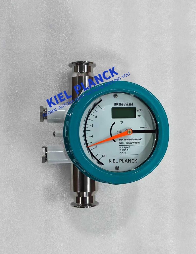
The installation of metal tube rotor flowmeters must strictly follow three core principles: vertical installation, fluid from bottom to top, and straight pipe sections meeting standards, to ensure measurement accuracy and long-term stable operation.
I. Pre-installation Preparation and Basic Requirements
1. Operating Condition Matching Confirmation
Media Adaptability: Check whether the measured medium (liquid or gas) is within the applicable range of the flowmeter, including parameters such as temperature, pressure, corrosivity, and viscosity.
Flow Range: Confirm that the actual flow rate is between 20% and 90% of the instrument’s range to avoid prolonged use at extremely low or excessive flow rates.
Flow Direction Marking: Verify the flow direction arrow on the flowmeter body; it must be consistent with the actual flow direction in the pipeline.
2. Straight Pipe Section Requirements
Standard Requirements: The flowmeter inlet should have a straight pipe section at least 5 times the pipe diameter, and the outlet should have a 250mm straight pipe section.
Special Operating Conditions: If there are disturbance sources such as valves, elbows, or pumps upstream, the straight pipe section should be appropriately lengthened or a rectifier should be installed.
High Precision Requirements: For applications requiring high precision, it is recommended that the inlet straight pipe section be ≥10 times the pipe diameter, and the outlet straight pipe section ≥5 times the pipe diameter.
II. Key Installation Steps and Specifications
1. Vertical Installation Specifications
Mandatory Requirement: Metal tube rotor flowmeters must be installed vertically, with an inclination not exceeding 2°.
Installation Calibration: Strict calibration using a level is required to ensure the meter body is completely vertical.
Incorrect Example: Horizontal or inverted installation is strictly prohibited, as this will cause the float to jam or result in severely inaccurate readings.
2. Pipeline Connection and Support
Connection Method: Connect the pipeline correctly according to the interface type (threaded, flanged, clamp, etc.) to avoid stress caused by forced alignment.
Pipeline Cleaning: Before installation, weld slag and debris must be thoroughly cleaned from the pipeline to prevent foreign objects from entering the flowmeter.
Support Requirements: For larger diameter or heavier flowmeters, supports should be installed on the pipeline. The flowmeter should not be used as a pipeline support.
3. Special Media Handling
Containing Magnetic Substances: If the medium contains ferromagnetic substances, a magnetic filter should be installed before the flowmeter.
Containing Solid Impurities: If the medium contains solid impurities, consider installing a filter between the valve and the straight pipe section.
Gas Measurement: Ensure the pipeline pressure is not less than 5 times the flowmeter’s pressure loss to ensure stable float operation.
III. Installation Points for Special Scenarios
1. High/Low Temperature Media
Temperature Range: Standard operating temperature -80℃~+200℃, high-temperature type up to 300℃
Jacket Design: If the temperature of the measured medium is higher than 220℃ or the fluid temperature is too low and crystallization is likely to occur, a jacketed flow meter should be selected.
Protective Measures: Avoid direct sunlight, high temperatures, humidity, or corrosive gas environments.
2. Hazardous Environment Applications
Explosion-proof Requirements: When used in flammable or explosive hazardous environments, a model with an appropriate explosion-proof rating must be selected.
Electrical Protection: Pay attention to the explosion-proof rating and electrical protection (IP rating). Special attention is required for models with remote transmission.
Installation Location: Should be located away from strong electromagnetic fields and areas of heat radiation to avoid magnetic field interference.
3. Bypass and Maintenance Design
Bypass Installation: For easy maintenance and replacement of the flow meter and cleaning of the measuring pipeline, a bypass pipeline and bypass valve should be installed.
Air Venting and Drainage: When measuring liquids, if the system may accumulate gas, an air vent valve should be installed at the highest point upstream of the flow meter; when measuring gases, if there is a risk of condensation, a drain port should be installed at the lowest point downstream.
Transparent Conical Tube: Glass rotor flow meters should be equipped with a protective cover to prevent accidental breakage; metal tube rotor flow meters do not have this concern.
IV. Post-Installation Inspection and Commissioning
1. Initial Inspection
Slow Opening: Slowly open the upstream and downstream valves to avoid water hammer or air hammer impacting the float.
Observe Operation: Observe whether the float rises smoothly without jumping or jamming.
Sealing Check: Check for leaks at the connections to ensure a good seal.
2. Calibration and Verification
Zero-point Calibration: Perform zero-point and range verification under stable operating conditions (follow the instructions).
Data Comparison: Compare historical data or standard meters to verify the reasonableness of the readings.
Signal Testing: If there is a pointer or electrical signal output, test whether the output signal is normal.
V. Common Errors and Preventive Measures
1. Typical Error Examples
Incorrect Installation Direction: Horizontal or inverted installation
Reversed Flow Direction: Flow from top to bottom instead of bottom to top
Insufficient Straight Pipe Section: Insufficient straight pipe section upstream of an elbow or valve
Pipe Stress: Pipe stress directly acts on the flowmeter body
Uncleaned Pipe: Installation without cleaning the pipe can cause the float to jam.
2. Preventive Measures
Strict Calibration: Use a level to ensure vertical installation.
Sufficient Space: Ensure sufficient straight pipe section; install a rectifier if necessary.
Regular Maintenance: Regularly check seals and clean the float and cone.
Professional Installation: Installation and commissioning by professional technicians are recommended.
Although metal tube rotor flowmeters have a simple structure, “vertical, bottom-up, and undisturbed flow field” are the three prerequisites for their accurate operation. By strictly following the above installation points and combining them with regular maintenance (such as cleaning the cone and checking the float’s flexibility), the flowmeter can be ensured to operate stably for a long time, providing reliable on-site flow indication and accurate data support for industrial process control.
Scan the QR code to receive more detailed information.





