

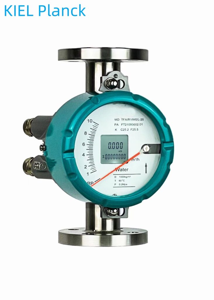
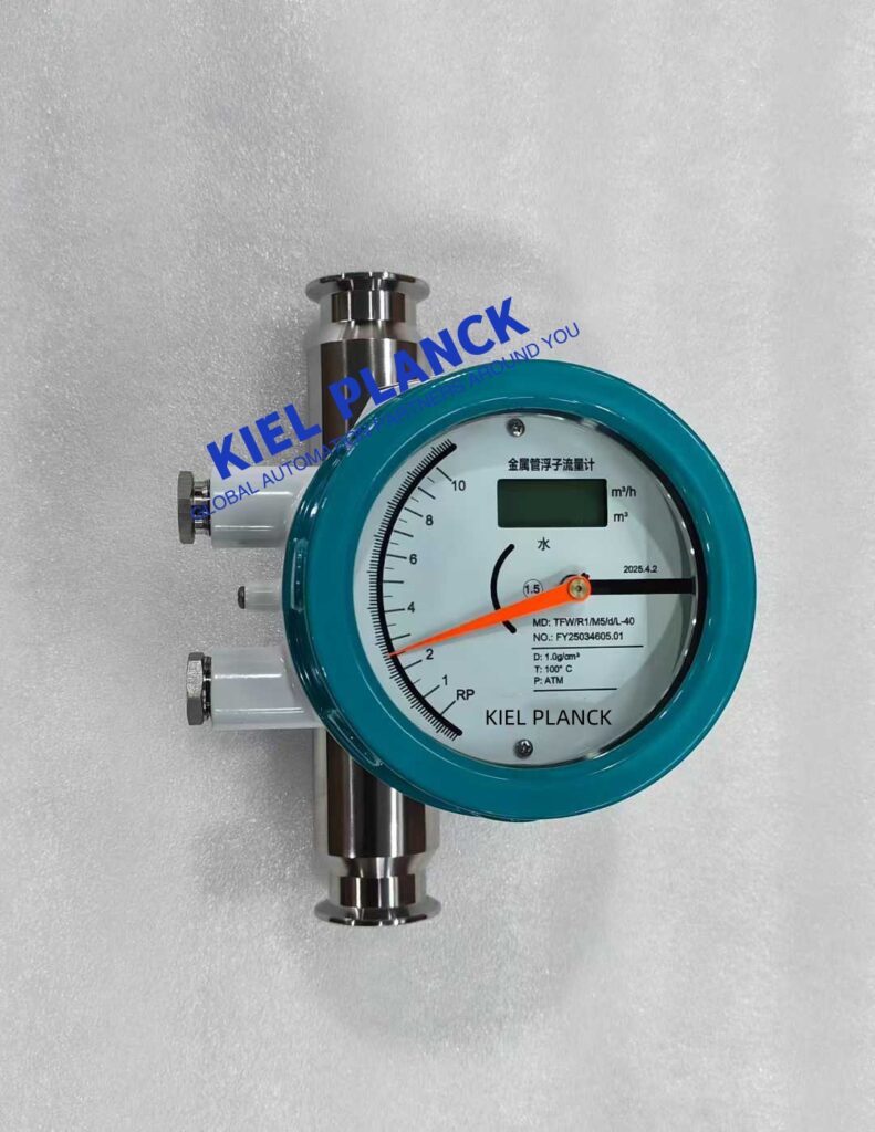
Metal tube rotor flowmeters (also known as metal float flowmeters) employ the variable area measurement principle, relying on the change in the float’s position within a tapered tube to directly reflect the flow rate. Features: simple structure, wide applicability, resistance to high pressure and high temperature, especially suitable for measuring small-diameter, low-velocity media.
I. Core Working Principle
Variable Area Measurement Mechanism
Composed of a vertically tapered tube and a float that can move up and down. Fluid flows from bottom to top through the measuring tube.
The float is subjected to lift, gravity, and buoyancy in the fluid. When lift and gravity are balanced, the float stabilizes at a certain height.
The float height is proportional to the flow rate. The flow rate can be determined by measuring the float’s position.
Signal Transmission Method
The float has a built-in high-performance magnet. Position changes are transmitted to an external indicator via magnetic coupling.
Non-contact transmission avoids the risk of fluid leakage and enables remote transmission.
It can output a 4-20mA standard signal and supports the HART communication protocol, facilitating integration into automation systems. II. Main Technical Features
Structural and Material Advantages
All-metal structure (stainless steel, Hastelloy, titanium, etc. optional), pressure resistance up to 25MPa, temperature range -80℃~400℃
Short stroke design, total instrument height only 250mm, small installation space
Magnetic coupling drive ensures stable signal transmission and avoids mechanical wear
Measurement Performance Characteristics
Wide range ratio: Standard type 10:1, special type up to 20:1 or even 50:1
High accuracy: Standard type 1.5 grade, special type up to 1.0 grade
Low pressure loss: Only 7kPa-70kPa, minimal impact on the system
Low requirements for straight pipe sections, flexible and convenient installation
Display and Output Functions
Dual-line large LCD display, capable of simultaneously displaying instantaneous flow and cumulative flow.
Optional models include on-site indication, remote transmission, corrosion-resistant, high-pressure, jacketed, and explosion-proof.
Supports two-wire, battery, and AC power supply to adapt to different field conditions.
III. Scope of Application and Advantages
Strong media adaptability
Can measure various media such as liquids, gases, and steam.
Suitable for harsh working conditions such as corrosive, high-temperature, high-pressure, flammable, and explosive environments.
Optional PTFE lining, resistant to strong acids and alkalis.
Wide range of applications
Chemical industry **Flow Rate Measurement:** 1. Chemical Raw Material Feed, Reaction Product Discharge, and Additive Flow Rate
2. Petroleum Industry: Flow rate measurement in crude oil, natural gas, water injection, and oil processing
3. Pharmaceutical and Food Industry: Liquid flow rate measurement during drug dissolution and mixing, and food sauce filling
4. Water Treatment: Flow rate measurement and process control under complex and harsh environmental conditions
**Maintenance and Reliability:**
Simple structure, no easily damaged electronic components directly involved in measurement
Low maintenance, service life of over 10 years
Features data recovery, data backup, and power-off protection to ensure data security
IV. Typical Technical Parameters
Measuring Range: Water (20℃) 2.5~100000 L/h; Air (20℃, 0.1013MPa) 0.07~4000 m³/h
Medium Viscosity: DN15: <5mPa·s; DN25: <250mPa·s
Ambient Temperature: LCD type -30℃~+85℃; Pointer type -40℃~+120℃
Connection Type: DIN2501 standard flange or flange specified by the user
Explosion-proof Marking: Intrinsically safe ExiaⅡCT6, Flameproof ExdⅡCT6212
Metal tube rotor flowmeters, with their simple structure, reliable measurement, and strong adaptability, have become indispensable flow measurement instruments in industrial automation process control. They are especially suitable for flow measurement scenarios involving small diameters, low flow velocities, and complex media, and are widely used in many industries such as petroleum, chemical, pharmaceutical, food, and water treatment.
Scan the QR code to receive more detailed information.





