

The blind zone of radar level gauges is usually between 0.1 and 0.5 meters. The specific size depends on various factors such as radar frequency, antenna type, medium characteristics and installation conditions. The blind zone of high-frequency radar is generally smaller than that of low-frequency radar.
I. Relationship between Blind Zone and Radar Frequency
High-Frequency Radar (80GHz and above)
Blind Zone Range: 0.1-0.3 meters (80GHz radar blind zone can be as small as 0.2 meters)
Advantages: High-frequency radar has a shorter wavelength, smaller beam angle (3°-6°), and more concentrated energy, resulting in a smaller blind zone.
Typical Applications: Scenarios requiring high precision, such as the food and pharmaceutical industries and small storage tanks.
Medium-Frequency Radar (26-70GHz)
Blind Zone Range: 0.3-0.5 meters (26GHz radar blind zone is typically 0.3 meters)
Features: Suitable for most applications. High cost-performance ratio for conventional industrial applications
Typical applications: Medium-sized storage tanks in industries such as petrochemicals and power generation
Low-frequency radar (6-26GHz)
Blind zone range: 0.4-0.6 meters
Advantages: Strong penetration capability, suitable for complex working conditions such as dust and foam
Typical applications: Cement plant powder silos, storage tanks containing foam, etc.
II. Relationship between blind zone and antenna type
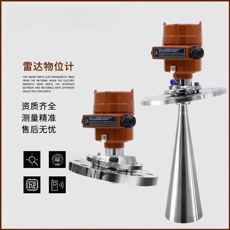
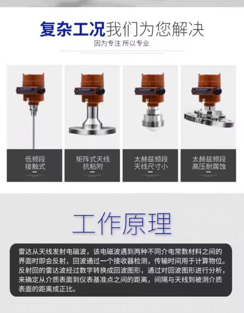
Non-contact radar (horn-mouth/flat panel antenna)
Blind zone range: 0.1-0.5 meters
Selection points: The larger the antenna size, the smaller the blind zone; the blind zone of a horn-mouth antenna is smaller than that of a pole antenna.
Typical parameters: 80G radar level gauge maximum blind zone is 0.2 meters
Guided wave radar (cable/pole type)
Blind zone range: 0.05-0.2 meters
Advantages: Smaller blind zone, suitable for low liquid level measurement
Limitations: Requires contact with the medium; not suitable for viscous or easily crystallizing media
Specially designed small blind zone radar
Blind zone range: 4-6 centimeters (measuring range is usually smaller, about 0.6 meters)
Applicable scenarios: Special occasions with limited space or requiring measurement of extremely low liquid levels
III. Factors affecting blind zone size Other Key Factors
Medium Characteristics
Low dielectric constant media (e.g., oil, liquefied gas): The blind zone needs to be appropriately increased (by 0.1-0.3 meters).
High viscosity or easily crystallizing media: The blind zone may need to be increased, requiring regular maintenance.
Foam or steam environments: Increased blind zone settings may be necessary to avoid interference.
Installation Conditions
Antenna to tank wall distance: Recommended to be 1/6-1/4 of the tank diameter (at least 300mm).
Antenna to obstacle distance: Should be greater than 0.5 meters to avoid false echo interference.
Installation Angle: The antenna axis must be perpendicular to the liquid surface; otherwise, the effective blind zone will increase.
Signal Processing Technology
Advanced echo processing algorithms effectively reduce the impact of blind zones.
The intelligent identification system can automatically read the tank structure, enabling easy obstacle avoidance.
IV. Practical Suggestions for Blind Zone Setting
Blind Zone Setting Principles
The blind zone must be larger than the equipment’s minimum blind zone requirement, but should not be too large to avoid wasting the measurement range.
The MAX liquid level should be lower than the lower limit of the blind zone to ensure measurement safety.
The measurement range should be set to 1.2-1.5 times the actual measurement height.
Blind Zone Adjustment for Special Scenarios
Overflow Protection Scenarios : Add a safety distance of 0.2-0.5 meters to the standard blind zone.
Containers with agitators: The blind zone must avoid the height of the agitator (e.g., if the obstacle is 0.4 meters from the antenna, the blind zone should be 0.5 meters).
Conical/concave tank bottoms: The blind zone must cover the unmeasurable area below the antenna.
Blind Zone Verification Methods
Simulation Test: Slowly pour material into the container and observe whether the instrument display responds normally outside the blind zone.
Actual Measurement: Measure the actual liquid level using a standard ruler and compare it with the instrument display value for verification.
Echo Curve Analysis: View the echo curve using professional software to confirm whether the blind zone setting is reasonable.
V. Impact of Blind Zone on Measurement and Countermeasures
Impact of Insufficient Blind Zone
Near-field interference and false detection: May lead to unstable measurement data
Signal processing difficulties: Difficulty in distinguishing between reflected and transmitted signals at close range
Solution: Appropriately increase the blind zone setting and optimize signal processing parameters
Impact of Excessive Blind Zone
Wasted measurement range: Inability to fully utilize the instrument’s measurement range
Limited low-level measurement: May be unable to accurately measure levels near the bottom of the tank
Solution: Select a radar model with a smaller blind zone or adjust the installation location
Practical Techniques for Optimizing Blind Zone
Use intelligent learning function: Allow the instrument to “learn” the current echo spectrum, identify and constrain interference
Adjust signal threshold: For media with low dielectric constants, appropriately lower the detection threshold
Use waveguide installation: Can significantly reduce the effective blind zone under complex operating conditions
In practical applications, the appropriate radar type and parameter settings should be selected according to the specific operating conditions. For beginners, it is recommended to follow the principle of “blind zone setting greater than the minimum blind zone requirement of the equipment, but not exceeding 5% of the measurement range,” and verify the rationality of the blind zone setting through actual testing. Regularly checking and calibrating the blind zone setting, especially when the characteristics of the medium or process conditions change, can ensure that the radar level gauge operates stably and reliably for a long time.





