

Acceptance criteria and methods for turbine flow meters
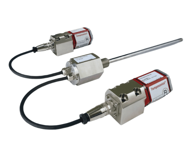
The acceptance criteria and methods for turbine flow meters mainly follow standards such as JJG 1037-2008 “Verification Procedure for Turbine Flow Meters”. Through technical document review, visual inspection, installation condition verification and performance testing, the accuracy, stability and applicability of the flow meter are ensured to meet the usage requirements.
Commissioning and Use of Turbine Flow Meters
The commissioning and use of turbine flow meters must strictly follow the installation specifications, commissioning procedures and operating requirements to ensure measurement accuracy and equipment lifespan. This mainly includes key aspects such as pre-installation preparation, correct installation, commissioning and calibration, standardized operation and regular maintenance.
Turbine flow meter installation and maintenance
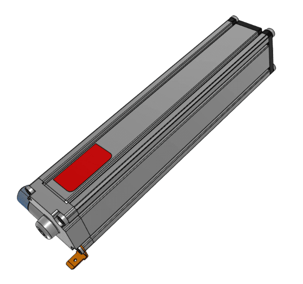
Turbine flow meters must be installed with sufficient straight pipe sections before and after the flow, filters must be added, they must be installed in the flow direction and vibration and interference must be prevented. Maintenance requires regular cleaning of the impeller bearings, inspection of wear and timely calibration.
Structural Analysis of Gas Turbine Flow Sensor
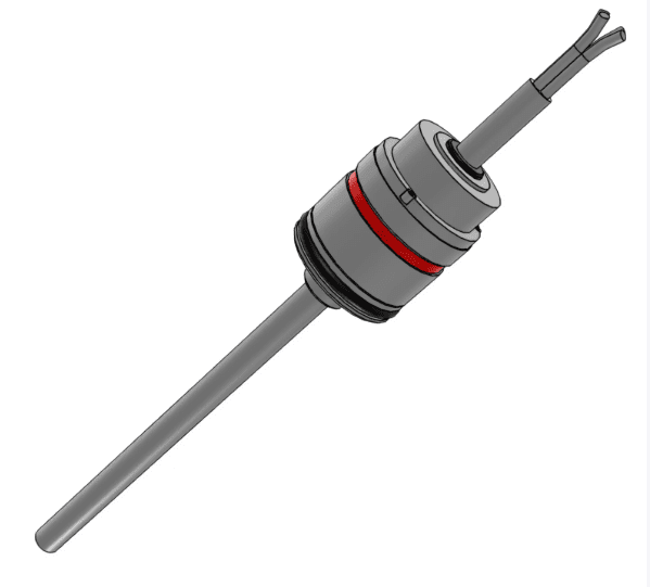
Gas turbine flow sensors are commonly used high-precision velocity-type flow measurement instruments in industry. They rely on the kinetic energy of gas to drive the impeller to rotate and achieve flow measurement.
Vortex flow meters solve the problem of air leakage control in beverage companies
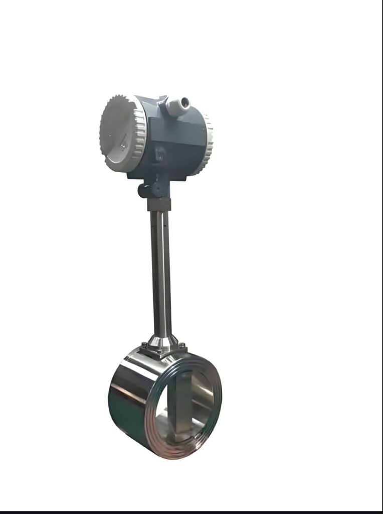
With its advantages of no mechanical wear, low pressure loss, high precision, wide range, and adaptability to clean working conditions, the vortex flow meter can accurately monitor the flow of compressed air in different zones and equipment, completely solving the pain point of air leakage control in beverage companies and helping factories save energy, reduce costs, and stabilize production.
High temperature and high pressure vortex flow meter industry
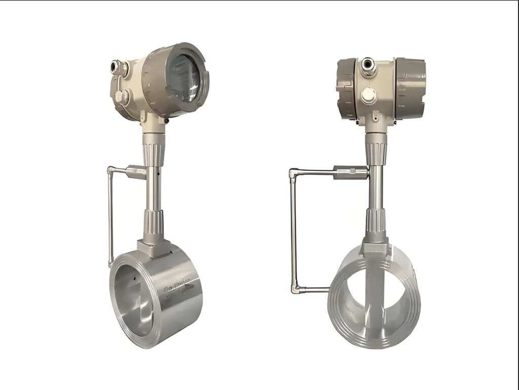
We propose a comprehensive solution for optimizing the efficiency of traffic monitoring, helping enterprises achieve accurate measurement, intelligent monitoring, cost reduction and efficiency improvement, and safe and stable production.
IP68 protected S1 radar level gauge
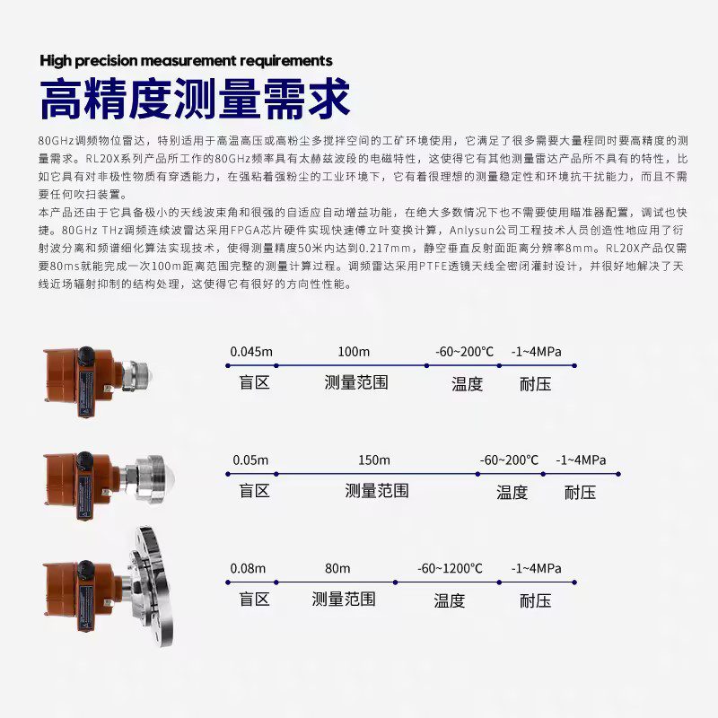
P68 Protective S1 Radar Level Gauge, Tank/Silo Radar Level Gauge, Non-Contact RS485 Radar Level Gauge, Two/Four-Wire 15-Meter Radar Level Gauge, Petrochemical Storage Tank Radar Level Gauge, Hydrological Monitoring Radar Level Gauge, Coal Mine Water Tank Radar Level Gauge
Measurement principle, advantages and disadvantages of radar level sensors
Radar level sensors achieve non-contact level measurement by transmitting, reflecting, and receiving microwave signals, offering significant advantages such as high precision, strong anti-interference capabilities, and adaptability to harsh environments.
What is the exact size of the blind zone of a radar level gauge?
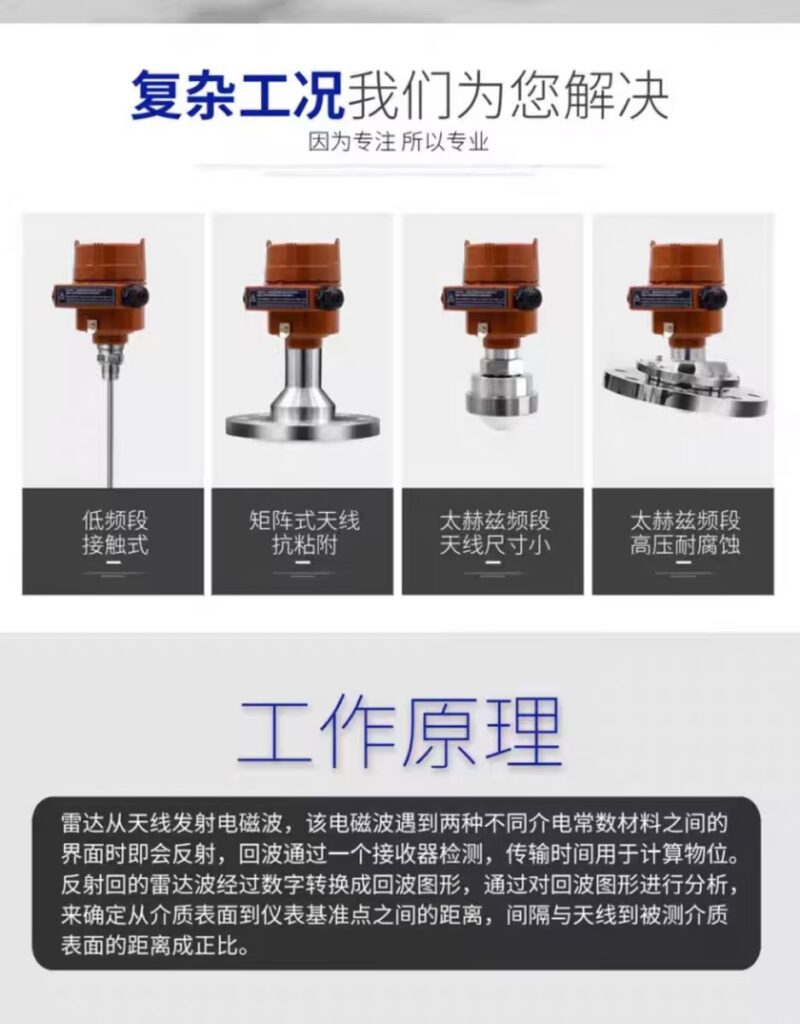
The blind zone of radar level gauges is usually between 0.1 and 0.5 meters. The specific size depends on various factors such as radar frequency, antenna type, medium characteristics and installation conditions. The blind zone of high-frequency radar is generally smaller than that of low-frequency radar.

