

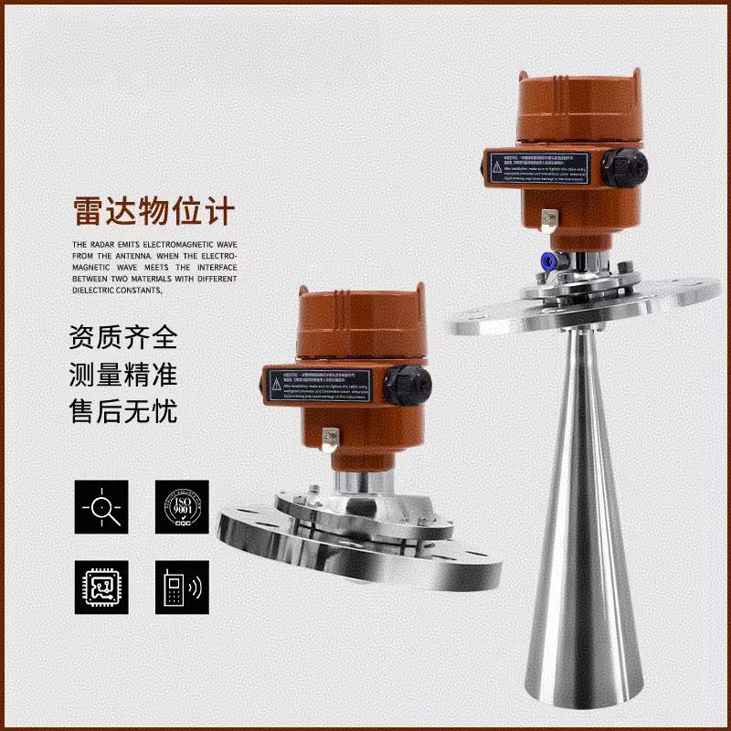
Radar level gauges achieve non-contact level measurement by transmitting, reflecting, and receiving microwave signals. They feature high accuracy, strong anti-interference capabilities, and wide applicability, and have become the mainstream choice for modern industrial level measurement.
I. Core Working Principle
1. Basic Measurement Principle
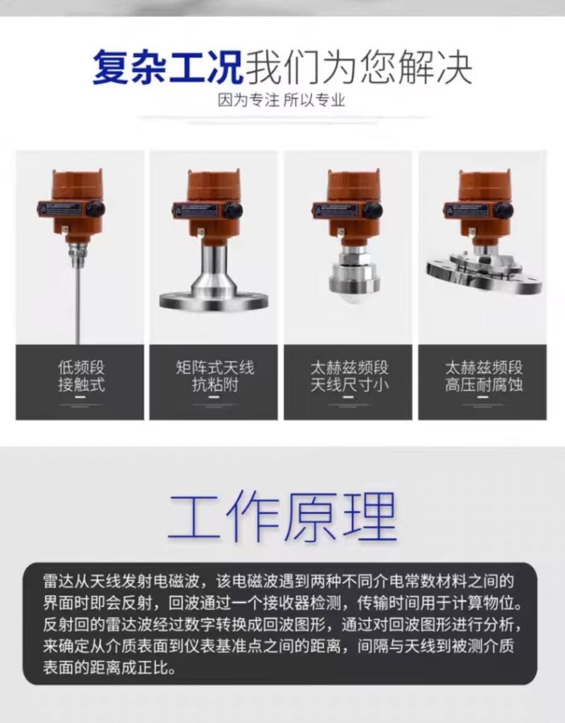
* **Transmission-Reflection-Reception:** The radar level gauge’s antenna transmits high-frequency electromagnetic waves (typically 6GHz-80GHz) to the surface of the measured medium. These waves are reflected off the medium surface and received by the antenna. The liquid level is determined by calculating the time difference between transmission and reception.
* **Mathematical Model:** Liquid Level = Total Container Height – Radar Wave Propagation Distance, where propagation distance D = C×T/2 (C is the speed of light, T is the time difference)
* **Measurement Formula:** Actual Liquid Level L = Empty Tank Height E – Radar Measurement Distance D
* **2. Technical Implementation Methods:**
* **Pulse Radar:** Uses short-pulse microwave signals, resulting in low energy consumption and a simple structure, suitable for medium-precision applications.
* **Frequency Modulated Continuous Wave Radar (FMCW):** Uses an 80GHz continuous frequency modulated waveform, providing more accurate ranging, a smaller beam angle (≤3°), and stronger anti-interference capabilities, suitable for high-precision and high-challenge scenarios.
* Guided wave radar: Microwave signals are transmitted along a metal probe or cable, making it particularly suitable for measuring liquids with low dielectric constants (such as liquid ammonia and liquid nitrogen).
II. Core Features of Radar Level Gauges
* 1. High-Precision Measurement
* Measurement Accuracy: Up to ±1mm, with 80GHz radar accuracy even controllable to ±0.5mm.
* Dynamic Range: 80GHz radar dynamic range reaches 120dB, far exceeding the 96dB of 26GHz radar, enabling the detection of weaker signals.
* Fast Response: Signal analysis and processing can be completed within 0.1 seconds, providing excellent real-time performance.
* 2. Advantages of Non-Contact Measurement
* No Wear or Contamination: The device has no direct contact with the measured liquid, avoiding sensor wear and clogging problems caused by liquid corrosion and high viscosity.
* Suitable for High Purity Requirements: It will not contaminate the measured medium, making it particularly suitable for industries with high purity requirements such as food and pharmaceuticals.
* No Mechanical Parts: Simple overall structure, no easily damaged components, and long service life (typically 8-10 years).
* 3. Environmental Adaptability
* Endurance to extreme conditions: Operating temperature range covers -40℃ to +250℃, and process pressure adaptability reaches 40 bar.
• Strong penetration ability: Can penetrate interfering media such as dust, steam, foam, and water mist, and is unaffected by surface foam and turbulence.
• Anti-interference capability: Immune to interference echoes caused by joints within the beam range and interference echoes caused by noise from feeding or discharging.
4. Wide Range of Applications
* **Media Types:** Meets liquids, particles, slurries, corrosive media, toxic media, high-viscosity liquids, and mud.
* **Vessel Types:** Suitable for spherical tanks, horizontal tanks, cylindrical tanks, cylindrical-conical tanks, storage tanks, buffer tanks, microwave tubes, bypass pipes, etc.
* **Industry Applications:** Widely used in petroleum, chemical, power, environmental protection, food, pharmaceutical, water treatment, metallurgy, textile printing and dyeing industries.
* **5. Intelligent and Convenient Features:**
* **Easy Installation:** Installed on top of the tank via threaded or flanged connections; no cooling measures are required when the installation height is above 800mm from the liquid surface.
* **Simple Maintenance:** Features fault alarm and self-diagnostic functions; faults can be quickly analyzed based on error codes.
* **Communication Functions:** Supports multiple signal output methods including 4-20mA, HART, RS485/Modbus, and Bluetooth, enabling remote monitoring.
* **Intelligent Debugging:** Some products are equipped with a mini-program operation, allowing debugging and parameter configuration via mobile phone, especially suitable for closed tanks or high-risk environments.
Typical Application Scenarios
* Petrochemical Industry: Measuring crude oil, diesel, gasoline, ethanol, etc. (explosion-proof certification required)
* Food and Beverage Industry: Used in syrups, beer, and dairy products (food hygiene certification required)
* Water Treatment Systems: Monitoring liquid levels in sewage tanks, sedimentation tanks, and inlet/outlet water outlets
* Pharmaceuticals and New Energy: Liquid level control in highly corrosive, ultra-high temperature, and confined containers
* Cement Industry: Stable measurement in 30-meter-high silos and high-dust environments
* Power Industry: Liquid level measurement of fly ash and limestone slurry
Selection Recommendations
1. Select frequency based on operating conditions: For complex operating conditions (dust, steam, foam), 80GHz radar is recommended due to its small beam angle (3°) and strong penetration.
2. Consider antenna material: For corrosive media, choose corrosion-resistant materials such as PTFE or Hastelloy.
3. Evaluate measurement range: For small-range measurements (≤30m), 26GHz is suitable; for large-range measurements (>30m), 80GHz is recommended.
4. Pay attention to protection rating: For harsh environments, choose products with IP67/IP68 protection rating.
5. Consider intelligent functions: For scenarios requiring remote debugging, choose products that support Bluetooth and mini-program operation.
6. Radar level gauges, with their high precision, non-contact measurement, and strong anti-interference capabilities, have become the standard equipment for modern industrial level measurement, especially performing far better than traditional measurement methods under complex operating conditions. With the continuous advancement of domestic technology, high-performance, cost-effective domestic radar level gauges can now rival imported brands, providing domestic enterprises with more high-quality options.





