

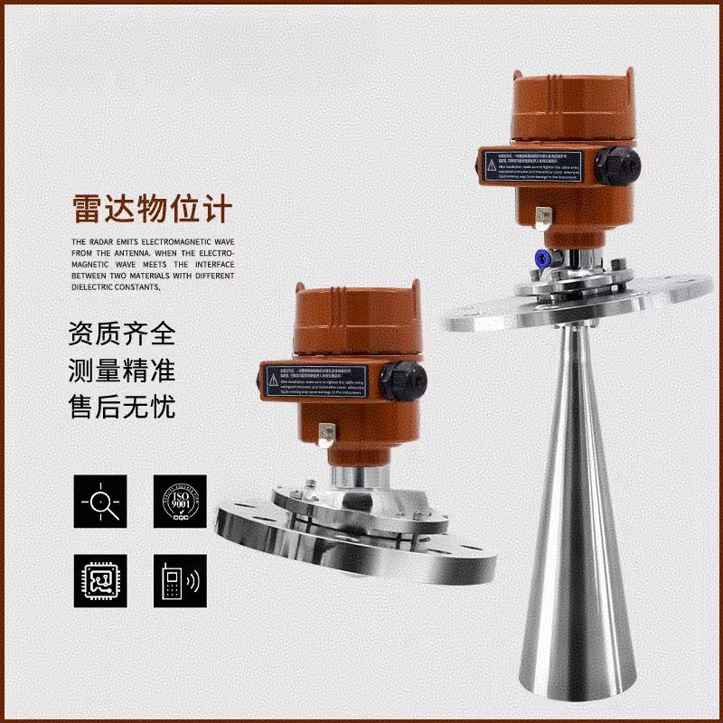
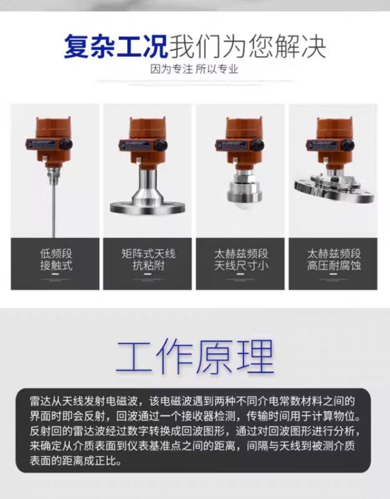
The commissioning of radar level gauges is a crucial step in ensuring their accurate measurement. It is mainly completed through three core steps: parameter setting, calibration, and verification. Appropriate commissioning methods and parameter values must be selected according to specific operating conditions.
I. Preparatory Work Before Commissioning
Check Installation Conditions
Confirm that the radar level gauge installation position meets the requirements: there should be no obstructions between the lower edge of the antenna and the surface of the measured medium, and within the beam radiation area.
Check Installation Angle: The flange’s error relative to the horizontal plane should be less than ±0.5°, ensuring the antenna’s central axis is perpendicular to the liquid surface.
Verify Cable Connection: Tighten the cable sealing cap; seal any unused electrical interfaces with blind plugs.
Confirm Equipment Status
Check Power Supply Voltage Stability: The power supply voltage is 24VDC; ensure correct polarity.
Confirm the equipment is undamaged, and the antenna surface is free of contamination or scale.
For high-temperature environments, confirm that the instrument’s “High-Temperature Mode” is activated.
II. Commissioning Methods and Steps
1. Three Main Debugging Methods
**Display/Button Debugging**
Debug the instrument directly using the four buttons on the display screen.
Advantages: Simple and intuitive operation, no additional equipment required.
Suitable Scenarios: Quick on-site debugging, simple parameter adjustment.
Operation Points: Press and hold the E button for 2 seconds to unlock the display unit, then select parameters using the -/+ buttons.
**Host Computer Debugging**
Connect the radar level gauge to a host computer via a HART adapter.
Advantages: More comprehensive parameter settings, echo curve viewing.
Suitable Scenarios: Debugging under complex operating conditions, requiring detailed analysis of echo signals.
Operation Points: Requires an RS232/USB interface, a HART adapter, and a 250Ω resistor.
**HART Handheld Programmer Debugging**
On-site debugging using a HART handheld programmer
Advantages: Highly portable, suitable for on-site operation
Applicable scenarios: On-site maintenance and debugging, especially in confined tank environments
Operation points: Models such as HBRD-909 support HART handheld programmers
2. Key Parameter Settings
Measuring Range and Upper/Lower Limit Settings
The measuring range must be greater than the actual measurement height of the tank (usually 0.5-2 meters higher).
Lower Limit: The distance from the radar probe flange to the lowest point, typically corresponding to a 4mA output point.
Upper Limit: The distance from the radar probe flange to the highest point, typically corresponding to a 20mA output point.
Example: Tank height 10 meters, measuring range set to 11 meters, lowest point set to 9 meters, highest point set to 1 meter.
Damping Time Settings
Static Liquid Level: Set to 0-2 seconds (default is usually 3 seconds).
Slight Fluctuations: Set to 2-10 seconds, balancing stability and response speed.
Severe Fluctuations: Set to 10-30 seconds, for periodic shaking caused by filtration and agitation.
Note: Excessive damping time can cause data “sluggishness” and may lead to misjudgments.
Media Parameter Settings
Water-based solutions: Set to DC4.
Other media: Set to DC1.9.
Special media: Need to be adjusted according to the actual dielectric constant.
Open and Full Calibration Settings
Empty Mark: Enter the empty mark distance E (distance from the reference point to 0% liquid level)
Full Mark: Enter the full mark distance F (level between 0% and 100%)
Practical Operation: When the tank is empty, the instrument display should be close to the “tank height” (error ≤ ±5mm)
3. Calibration Methods
Zero Point Calibration
Perform calibration when the liquid level is zero to ensure accurate measurement starting point.
Operation: In the empty tank state, adjust the zero point parameter to make the displayed value consistent with the actual height.
Full Scale Calibration
Perform calibration when the liquid level is full to ensure accurate measurement endpoint.
Operation: When the tank is full or the liquid level is known, compare with the actual liquid level and fine-tune the “range” parameter.
Reference Point Calibration
Set a reference point at the full scale for single-point calibration.
Advantages: Does not affect normal production, short distance at full scale, high reflection intensity.
Operation: Using a radar level gauge Calibration is performed by comparing the actual measurement at the reference point with the known value.
Manual Calibration
Tools needed: A graduated stainless steel measuring rod for liquids (accuracy ±1mm).
Select calibration points: Choose three points within the radar’s commonly used range (e.g., for a range of 0-10m, select 2m, 5m, and 8m).
Manual measurement: Insert the measuring rod vertically into the medium until it reaches the bottom of the tank, and read the height of the medium mark (repeat three times and take the average).
Data comparison: Compare the manually measured “true level value” with the radar display value. Correct the error if it exceeds the allowable range.
III. Post-Debugging Verification and Maintenance
Verification Steps
Simulate the liquid level rise and fall process to check if the level gauge responds promptly and accurately.
Observe the display screen and check the liquid level data. Adjust promptly if any abnormalities are found.
Set the alarm function threshold and conduct testing to ensure normal alarm function when the liquid level is abnormal.
Common Problems and Solutions
Large data fluctuations: Check the damping time setting, increase the damping time, or check the installation location.
Weak signal: Check if the antenna is contaminated and clean the antenna surface.
Large measurement error: Recalibrate the zero point and full scale, and check if the range setting is reasonable.
Communication abnormalities: Check if the wiring is correct and if the power supply voltage is stable.
Regular Maintenance
Daily Inspection: Regular inspection Power supply voltage, output current, and antenna cleanliness (whether it is contaminated).
Regular Calibration: The manufacturer recommends an initial calibration cycle of 1 to 2 years; for critical applications, this can be shortened to 6 months.
Antenna Cleaning: Clean the antenna regularly to prevent scaling that could affect measurement accuracy.
IV. Special Operating Condition Adjustment Recommendations
High-Viscosity Media (e.g., Asphalt)
Installation Location: ≥1.5 meters from the inlet to avoid asphalt splashing and contaminating the probe.
Blind Zone Setting: Set to ≥10cm to avoid interference from bottom residue.
Regular Inspection: Check the probe for coking every 3 months.
Foamy Media
Select a low-frequency radar level gauge for better foam penetration.
Increase the damping time to 8-15 seconds to filter fluctuations caused by foam.
High-Temperature Environment
Select a high-temperature model and confirm the temperature resistance of the seals (e.g., use fluororubber gaskets).
Cables must be high-temperature resistant (e.g., silicone rubber cables, with a temperature resistance of 180℃ or higher).
Confirm that the high-temperature mode is enabled during commissioning.
When commissioning the radar level timer, follow the basic principle of “lower limit < tank height, range > tank height,” and adjust parameters according to specific operating conditions. For beginners, it is recommended to start with the default values, observe data changes, and then make small adjustments to gradually find the most suitable settings for the on-site conditions. After commissioning, continuously monitor for a period of time to ensure stable equipment operation.





