Blog
Cooling Water Flow Monitoring for Vacuum Sintering Furnaces
Reliability Enhancement and Fault Early-Warning Design for the Cooling Water Flow Monitoring System of Vacuum Sintering Furnaces
Reliability Enhancement and Fault Early-Warning Design for the Cooling Water Flow Monitoring System of Vacuum Sintering Furnaces
Water Flow Switches vs. Flow Meters: A Technical Comparison of Cooling Water Monitoring Solutions for Vacuum Furnaces
acuum debinding and sintering is a critical process for preparing high-density and high-purity metal and ceramic materials. The furnace needs to complete low-temperature debinding and high-temperature sintering in a continuous vacuum environment, with the internal temperature soaring up to hundreds or even thousands of degrees Celsius. Long-term high-temperature operation will generate a large amount of radiant heat and conductive heat, which poses a serious threat to precision components such as furnace door sealing rings, cooling jackets and vacuum pumps.
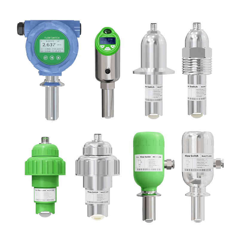
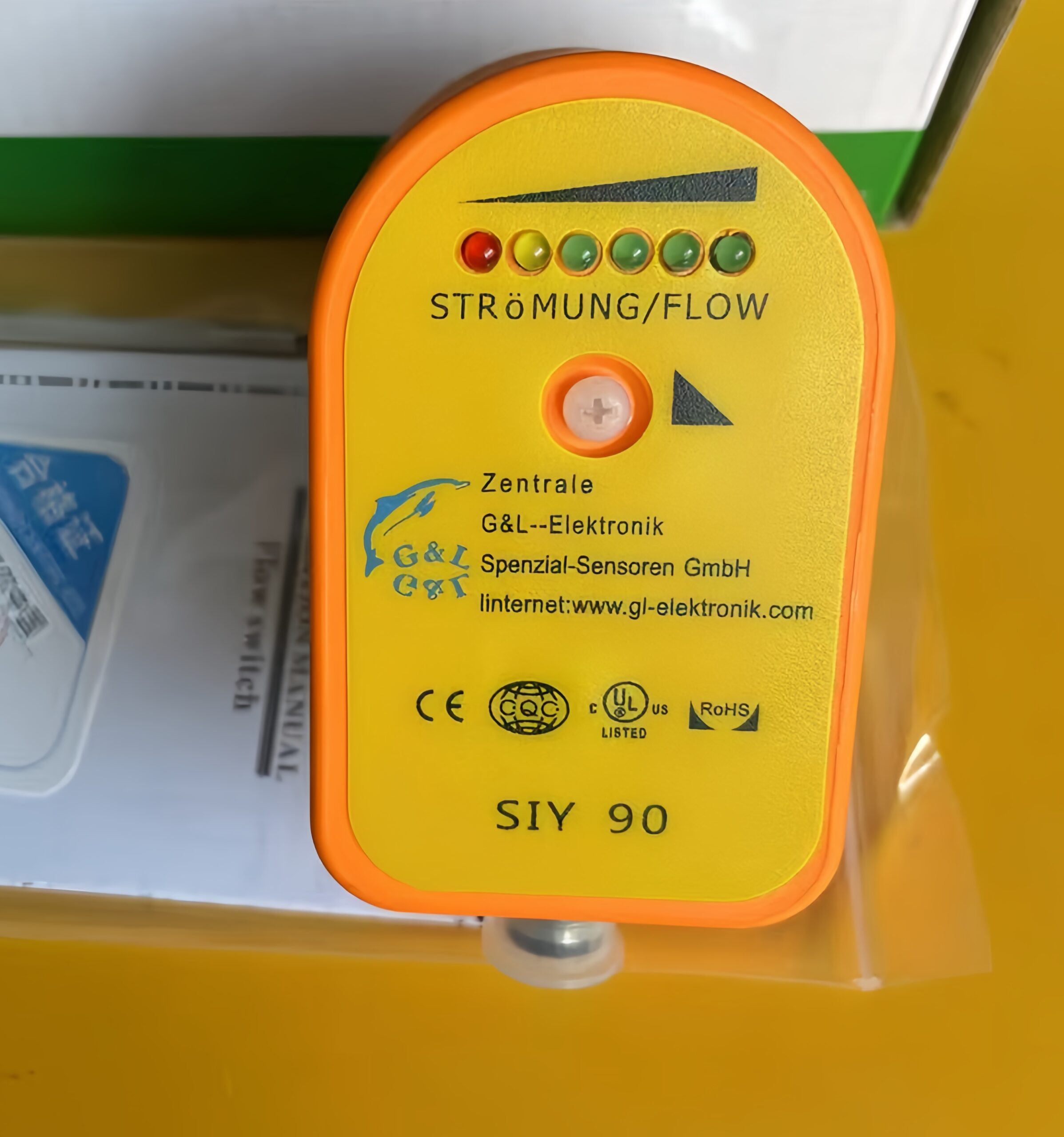
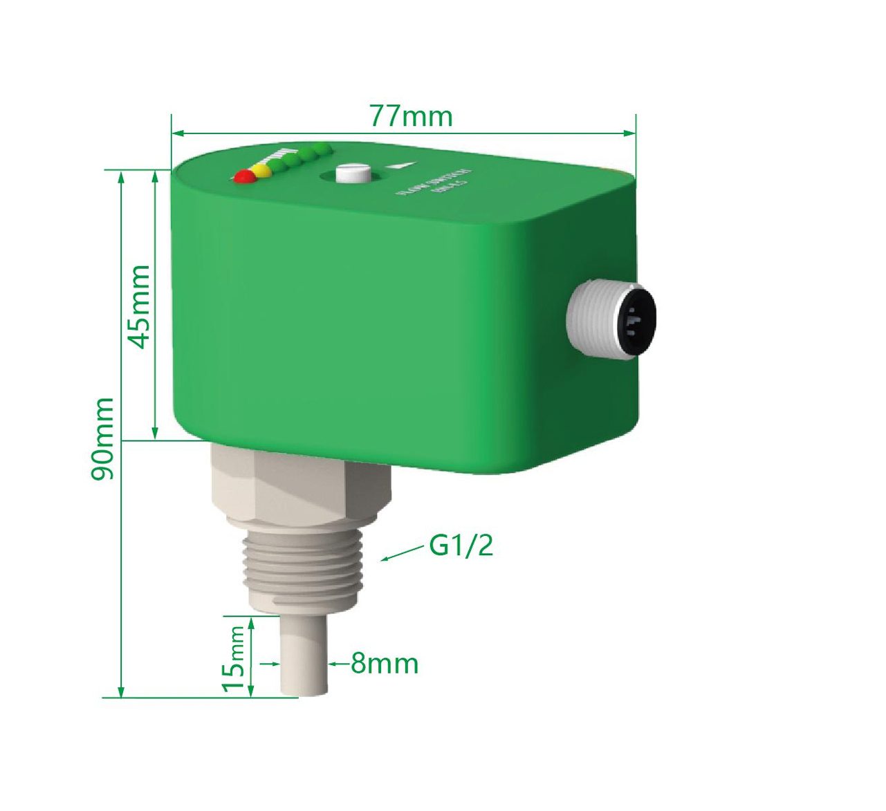
Vacuum sintering furnaces rely on stable cooling water systems to dissipate high-temperature heat generated during sintering processes and ensure equipment operational safety and product sintering quality. As a core safety monitoring component, water flow switches undertake real-time flow detection and fault alarm functions, whose reasonable selection and standardized installation directly determine the stability and failure resistance of the entire cooling system. This paper analyzes the operational characteristics of vacuum sintering furnace cooling water systems, summarizes key selection criteria for water flow switches applicable to high-temperature and impurity-containing industrial water environments, and elaborates standardized installation specifications, commissioning steps and common error prevention measures.
Diaphragm compressors are critical core equipment for high-purity hydrogen pressurization, widely applied in hydrogen energy storage, chemical manufacturing and new energy industries. Real-time online monitoring of operating status is essential to prevent diaphragm fatigue failure, pressure fluctuation abnormality and system shutdown faults. Pressure parameters serve as the most intuitive and effective characteristic indicators to reflect the operating state of diaphragm compressors, including inlet and outlet pressure, cavity balance pressure and instantaneous pulsating pressure.
Diaphragm hydrogen compressors rely on metal diaphragms to isolate mechanical transmission components from high-pressure hydrogen medium, which is the core guarantee for oil-free, high-purity and leak-free hydrogen compression. Diaphragm rupture and micro-leakage are the most common hidden safety hazards in compressor operation, which may cause hydrogen medium leakage, system pressure drop and even flammable and explosive risks if not detected in time.
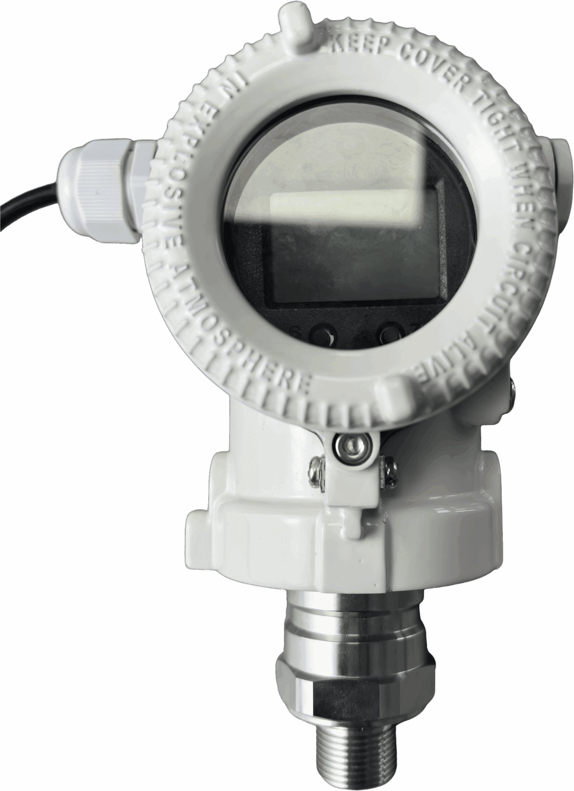
Diaphragm hydrogen compressors are core equipment for high-purity and high-pressure hydrogen delivery, widely adopted in hydrogen refueling stations, chemical hydrogen production and industrial precision pressurization systems. Outlet pressure monitoring is the key link to ensure stable compressor operation, avoid overpressure risks and guarantee consistent hydrogen supply quality. Pressure transmitters serve as the core sensing device for outlet pressure measurement, and their type selection and field application directly determine the accuracy, stability and safety of the whole monitoring system.
Diaphragm hydrogen compressors are core equipment for high-purity hydrogen pressurization and transportation, widely used in hydrogen energy, petrochemical and new energy industries, featuring zero leakage and high-pressure compression performance. Pressure transmitters are critical monitoring components for compressor outlet pressure, cavity pressure and system operating status, whose measurement accuracy and operational stability directly determine the safe and efficient operation of diaphragm hydrogen compression systems.
High-pressure hydrogenation technology is widely applied in petrochemical refining, coal chemical conversion and new energy hydrogen production industries, where pressure transmitters serve as core monitoring instruments for process pressure control and safety early warning. The extreme operating conditions of high pressure, pure hydrogen medium, high temperature and alternating load in hydrogenation processes easily cause measurement drift, structural aging and performance degradation of pressure transmitters, seriously affecting the long-term operational stability and safety of industrial systems.