

The customer asked why the tuning fork switch on his reactor kept malfunctioning
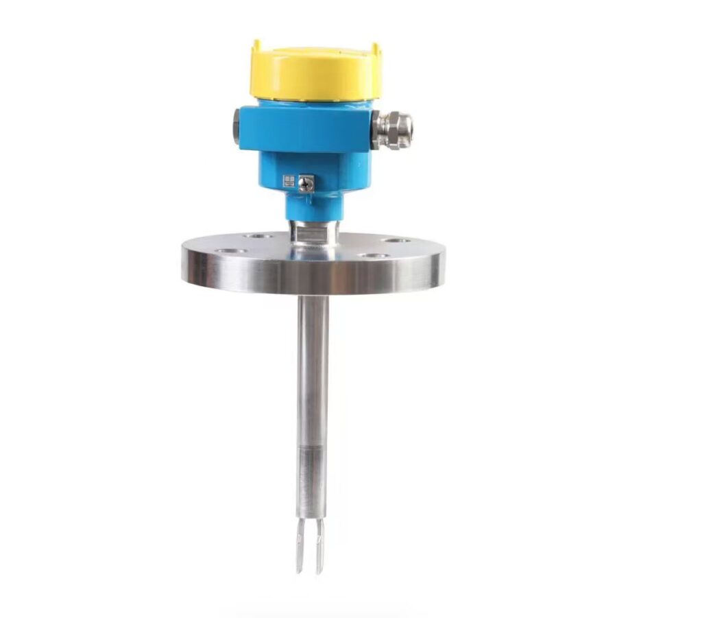
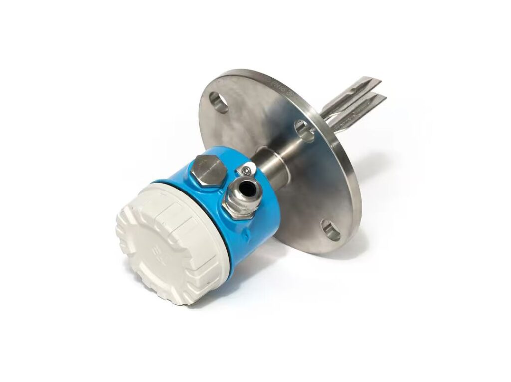
In chemical and industrial production, tuning fork switches are essential level measurement devices widely installed on reactors to monitor liquid or solid material levels and ensure stable and safe operation of production equipment. Recently, a customer reported frequent malfunctions of the tuning fork switch equipped on his production reactor, including inaccurate level detection, delayed signal feedback and occasional false alarms, which seriously interfered with the normal production schedule and raised potential safety hazards. To solve this problem effectively, it is necessary to analyze the root causes of the malfunction and summarize targeted solutions based on practical working conditions.
There are several common core reasons for the continuous malfunction of reactor tuning fork switches. First, material adhesion and fouling are the most prevalent causes. Reactors are mostly used for chemical reaction, mixing and material processing, and the internal materials are often viscous, granular or easy to crystallize. Long-term operation will lead to material accumulation on the tuning fork probe. The adhered substances change the vibration frequency of the tuning fork, causing the sensor to fail to accurately identify the material level state, thus triggering misjudgment and frequent malfunctions.
Second, inappropriate installation and structural interference will also affect the working performance of the switch. If the tuning fork switch is installed too close to the reactor wall, stirring paddles or feeding and discharging pipelines, the vibration generated by the reactor’s stirring operation and material flow will interfere with the inherent vibration of the tuning fork. This external vibration interference will confuse the sensor’s judgment signal, resulting in unstable operation and continuous faults. In addition, improper installation angle and loose fixation will also aggravate the malfunction problem.
Third, harsh operating environment and parameter mismatch will shorten the service life of the switch and cause failures. The internal environment of the reactor is usually characterized by high temperature, high pressure or corrosive gas. If the selected tuning fork switch does not match the reactor’s working parameters such as temperature, pressure and corrosion resistance, the internal circuit and sensor components will be damaged gradually. Moreover, excessive material impact in the reactor during production will cause mechanical wear of the tuning fork probe, affecting its normal vibration induction function.
Fourth, electrical and circuit faults are also key inducing factors. Long-term operation may lead to aging of the switch’s internal circuit, loose wiring terminals, poor contact or water and dust ingress into the junction box. These electrical problems will cause unstable power supply and signal transmission failure, making the tuning fork switch unable to work normally and resulting in frequent intermittent malfunctions.
To resolve the above malfunctions, targeted maintenance and optimization measures can be adopted. Regular cleaning of the tuning fork probe is the most basic maintenance measure, which can effectively remove adhered materials and restore the normal vibration frequency of the probe. For installation problems, workers should recheck and adjust the installation position and angle of the switch to avoid mechanical interference from reactor accessories and ensure firm fixation. It is also necessary to verify the model and parameter adaptability of the switch, and replace it with a high-temperature and corrosion-resistant tuning fork switch that matches the reactor’s working conditions if needed. In terms of circuit maintenance, regular inspection of wiring tightness, replacement of aging lines and sealing of the junction box can stabilize signal and power supply.
In conclusion, the frequent malfunction of the reactor tuning fork switch is mainly caused by material fouling, improper installation, mismatched working conditions and electrical faults. Regular daily maintenance, standardized installation and parameter matching can effectively avoid most failure problems. Timely troubleshooting and targeted maintenance can quickly restore the normal working state of the switch, guarantee the continuous and stable operation of the reactor, and reduce production losses and safety risks for enterprises.
Scan the QR code to receive more detailed information.





