

Once a Year: On-Site Verification Procedures for Transmitter Zero and Span Adjustment
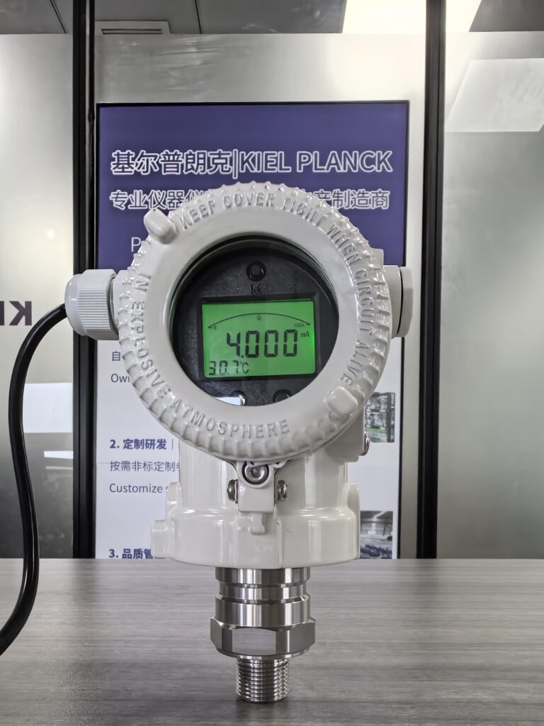
Process transmitters, including pressure, differential pressure and level transmitters, serve as core signal sources for industrial process control systems. Affected by long-term temperature drift, mechanical stress, medium corrosion and aging of electronic components, their zero point and span will gradually deviate after one year of continuous operation, leading to inaccurate process data and biased automatic control.
Starting from October, Essential Tips for Northern Projects: Five Key Details for Pressure Transmitter Winter Freeze Protection
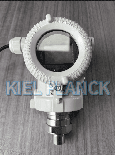
Pressure transmitters deployed in northern industrial sites face severe freezing risks as temperatures drop starting in October. Frozen process media inside impulse pipes, sensor cavities and capillary assemblies often lead to blocked pressure transmission, diaphragm rupture, permanent sensor damage and process interlock failure.
What Questions to Ask Before Purchasing a Pressure Transmitter
Pressure transmitters are foundational measurement instruments widely used in petrochemical, new energy, pharmaceutical and water treatment industries. Improper selection often leads to inaccurate readings, premature corrosion, seal failure and unexpected shutdown losses.
Fixed-Point Level Detection of Tuning Fork Level Switches for High-Viscosity Glue and Pulp Working Conditions
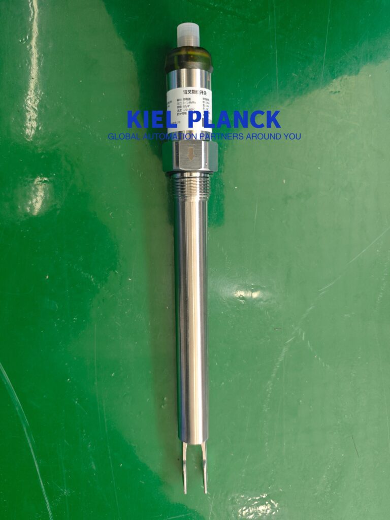
High-viscosity glue and paper pulp are typical non-Newtonian viscous media widely applied in packaging, papermaking, and chemical industries. Such media have prominent characteristics of high consistency, strong adhesion, and easy wall hanging, which bring severe challenges to traditional level detection equipment
Tuning Fork Level Switches for High and Low Level Alarm of Storage Tanks with Flammable and Explosive Media
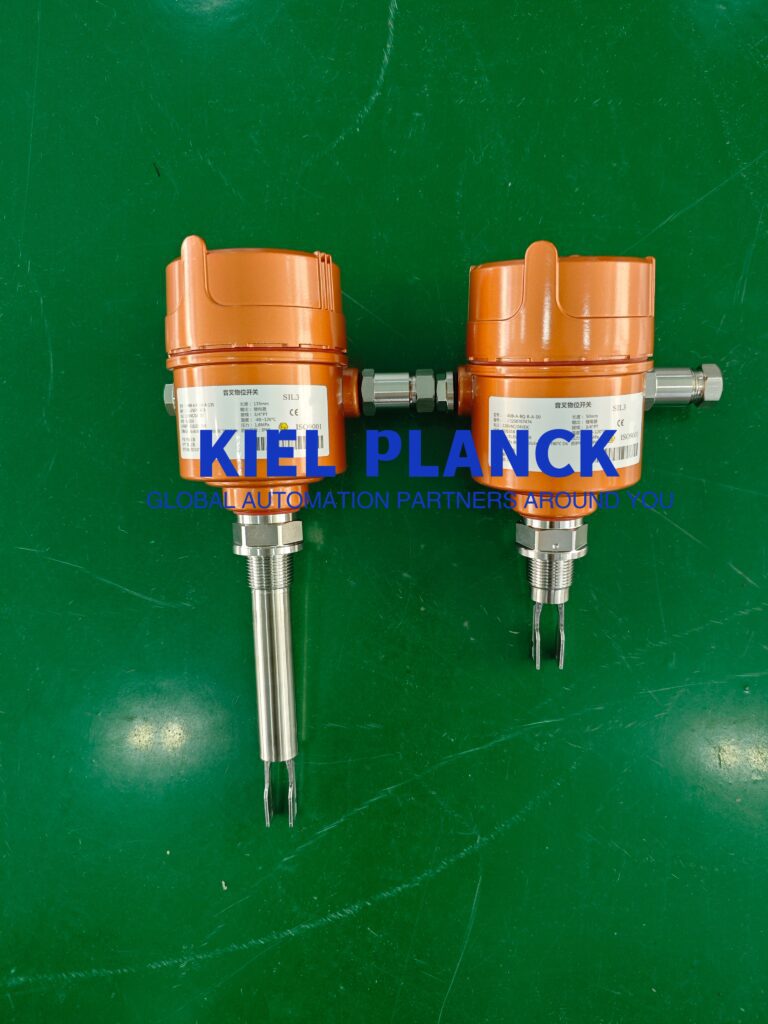
Flammable and explosive media such as organic solvents, fuel oils and chemical volatile liquids are widely stored in industrial storage tanks, posing severe safety risks of leakage, overfilling and explosion. High-precision and reliable high and low liquid level alarm is the core safety barrier for tank area operation.
Tuning Fork Level Switches: An Alternative to Floating Ball Failure for High-Turbulence Reactor Working Conditions
Chemical reaction kettles are core process equipment for mixing, synthesis, and material reaction in fine chemical, pharmaceutical, and new energy industries. The continuous stirring, circulating feeding, and violent liquid fluctuation inside the reactor form strong turbulent flow, which has long been a key cause of frequent failure of traditional floating ball level switches.
Tuning Fork Level Switches Adapted to CIP Cleaning Scenarios in Food and Pharmaceutical Sanitary Working Conditions
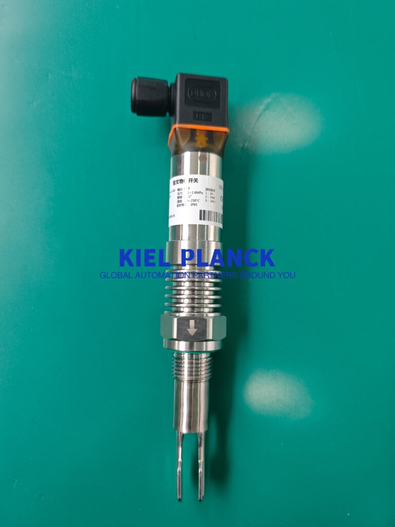
Food and pharmaceutical production industries require strict sanitary control and standardized cleaning procedures to ensure product safety and batch consistency. Cleaning in Place (CIP) is an essential automatic sterile cleaning technology for production tanks and pipelines, featuring high-temperature flushing, alternating chemical detergent scouring and frequent medium switching.
Tuning Fork Level Switches Solve Pump Dry-Run Interlock Problems in Impurity-Containing Sewage and Slurry Conditions
Sewage and slurry transportation systems are core facilities in environmental protection, chemical industry, municipal engineering and mining fields. The medium contains a large number of solid impurities, suspended particles and sediments, bringing severe challenges to liquid level monitoring and pump safety interlock control.
Tuning Fork Level Switches: Reliable Liquid Level Monitoring Unaffected by Bubble Disturbances in Complex Bioreactor Working Conditions
Biological fermentation tanks (bioreactors) are core production equipment for biopharmaceuticals, probiotic fermentation, and biological enzyme synthesis, featuring complex operating conditions such as continuous aeration stirring, microbial metabolism, and frequent bubble and foam generation.

